 English resume
Sensors
New monitoring technologies facilitate real-time monitoring and evaluation of dike performance and generate data that contribute to a better understanding of dike status regarding strength and condition.
|
Thema |
Waterveiligheid, Delta facts, English versions |
|
Tags |
B&O waterkeringen monitoring primaire keringen regionale keringen |
|
Downloads |
- INTRODUCTION
- RELATED TOPICS AND DELTA FACTS
- MULTILAYER SAFETY STRATEGY
- SCHEMATIC
- TECHNICAL SPECIFICATIONS
- GOVERNANCE
- COSTS AND BENEFITS
- LESSONS LEARNED AND ON-GOING STUDY
- KNOWLEDGE GAPS
- EXAMPLE OF IJKDIJK ACTIVITIES
Introduction
A sensor is a monitoring technology that measures physical quantities. New monitoring technologies facilitate real-time monitoring and evaluation of dike performance and generate data that contribute to a better understanding of dike status regarding strength and condition. The monitoring systems allow for more accurate strength calculations that will help improve safety through early detection of structural weaknesses that could compromise dike integrity. These technologies are also expected to reduce the cost of design, maintenance and dike improvements as these can be achieved more efficiently through the higher level of precision with which management, design and reinforcement parameters can be calculated. A monitoring system can provide valuable real-time information about the most divergent parameters in a relatively cost-effective manner.
Measurement technologies contribute to:
- Inspection/management
- Safety assessment
- Risk management through real-time inspection of dikes after rejection and before reinforcement
- Optimisation of reinforcement design of rejected dikes
- Early warning
- Optimisation of long-term management and maintenance
Related topics and Delta Facts
Keywords: monitoring techniques, measurement technologies, Flood Control 2015, IJkdijk, LiveDijk, UrbanFlood, SBW programme, HWBP.
Delta Facts: x
Multilayer safety strategy
Multilayer safety can be categorised into three main areas:
1 Prevention, 2 Spatial Planning, 3 Crisis Management
Monitoring systems fall under the first layer, prevention, as they can contribute to the dike strength assessment. In the event of imminent dike failure, monitoring techniques can be allocated to the third layer, crisis management, as they can be applied in operational flood management.
Schematic
Monitoring systems can be categorised into two types: local/in-situ (inside the dike) and remote sensing/ex-situ (outside the dike). In-situ instruments are embedded in the ground inside the dike and typically measure a single point or along a line. Remote sensing (ex-situ) instruments are designed to take measurements from a remote location (land-based, airborne and satellite), for example to determine deformations, which can serve as an indication for the dike behaviour. Sensors on the dike surface are sometimes used for in-situ and sometimes for remote sensing applications. Measurements carried out on the dike for surface deformation and cracking, for instance, are in-situ, whereas geophysical measurements from the surface into the depths of the dike are generally considered remote sensing.
Such measurements can help determine dike strength, and the various failure mechanisms that could compromise it, more accurately than previously possible. Monitoring, in this context, can therefore be defined as repeated and frequent measurements that can be used to take potentially appropriate management measures, where necessary. There is, however, a distinction to be made in the frequency with which measurements are taken; multiple times or over a period of time. Through monitoring, parameters can be measured directly or indirectly. Temperature, for example, can be used as a measure of groundwater flow and is therefore an indirect measurement.
Measurements can also be made at specific points (discrete), or more continuously across a single line (one-dimensional) or along a plane (two-dimensional). For instance: temperature measurements with fibre optic cables can take place at specific points on the cable (discrete) or at one-metre intervals along the entire length of the cable (continuous) - in which case, an average value is obtained.
Measurements can be taken on different scales, see figure below.
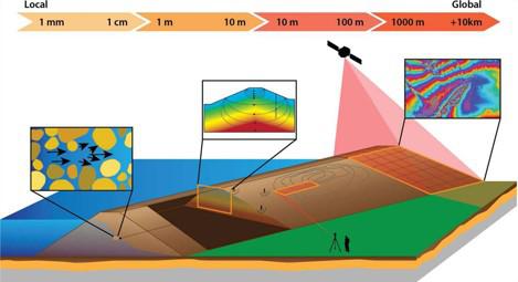
Adapted from Mooney (2011).
Sensors are connected to a readout unit, which processes the data collected from the sensors and transmits them for analysis. Based on the findings of the analysis, action will be taken if required. This is the way in which monitoring systems can contribute to water safety. The figure below shows how the system works:
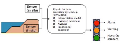
A possible tool for interpretation is data-driven modelling, which enables detection of changes in dike behaviour under similar loads. The premise is that action must be taken when abnormal dike behaviour is observed. The change in dike behaviour can be seen in fluctuating monitoring results.
Technical specifications
The table below shows the application, parameter and nature/characteristics of different types of sensors.
| Type of measurement technology (sensor) | Type of measured parameter | Important for type of failure mechanism 1. piping 2. heave 3. macro-instability 4. overflow and overtopping 5. micro-stability | In-situ (I) or Remote Sensing (RS) | Maximum frequency of measurement | Other observations |
| Satellite | Deformation, temperature, moisture content | 1, 2, 3, 5 | RS | Approx. once every two weeks (subject to availability) | For example INSAR, DIFSAR |
| Infrared (thermal camera) | Temperature | 1, 4 | RS | Once per second | |
| Inclinometer | Deformation | 3, 5 | I | Once per 10 seconds | |
| Water pressure gauge | Water pressure, temperature | 1, 2, 3, 4, 5 | I | Up to 500 times per second | Frequently used type: piezometer |
| Self potential | Electrical load | 1, 5 | I/RS | Once per minute | Passive and active (self potential) form |
| Fibre optic or synthetic cable | Deformation, temperature, water pressure | 1, 3, 5 | I | Once per 10 seconds | Usually only temperature. |
| Total station | Deformation | 2, 3, 5 | RS | One point per 10 seconds | Type of surveying. Can survey several points from one location |
| Microphone/Hydrophone | Noise | 1, 3, 4 | I/RS | X | 1-50,000 Hertz |
| Subsidence measuring hose | Deformation | 3 | I | Once per second | Only vertical deformation |
| Subsidence marker /Settlement plate | Deformation | 3 | I | Once per minute | |
| Laser measurements | Deformation | 3 | RS | 20 points per second | For example LIDAR |
| Tilt sensor | Deformation | 3 | I | Once per second | Only indicative |
| Inverted Pendulum | Deformation | 3 | I | Once per minute | Only horizontal deformation, high-precision, but limited measurement range |
| Moisture gauge | Moisture content | 3, 4, 5 | I/RS | Once per second | Important element for rapid water level drop |
| Geophysical measurements | Soil properties (moisture content, porosity, volume weight, electrical conductivity, wave propagation velocity) | 1, 2, 3, 4, 5 | RS | situational | For example TDR, GPR, ERT, MRS, radioactivity measurement, PMR |
Note: Some degree of extrapolation is always necessary to assess dike behaviour under normative conditions. (Koelewijn, 2011). See also Inspection of flood defences: an overview of measurement techniques (STOWA; 2010).
Governance
Water boards can avoid liability by adopting the standard in good time. Monitoring can alert water boards to the increased risks of a (rejected) dike. Use of monitoring and application of new technologies can serve as proof that every reasonable effort has been made to meet the duty-of-care obligation to provide an effective flood defence system. For more information, see juridification of inspections and the water board.
The Netherlands is the global leader in large-scale testing and development of dike monitoring systems and is looking to apply this knowledge in other countries.
Costs and benefits
Different selection criteria/conditions/goals are in place to determine whether sensor technology should be used to monitor dikes:
- Dike does not meet the standard (rejected)
- Dike meets the standard, but the manager still has reason to monitor it
- Obtain more information about dike behaviour in preparation for reinforcement; optimisation of dike design
- Optimisation of management and maintenance
- Automatic safety assessment (strength calculation)
The selection of a sensor involves a number of important factors:
- Normative failure mechanisms and associated uncertainties
- Water level/pressure and geographical structure
- Dike revetment
- Price
- Reliability
- Economic useful life
- Installation options
Cost-determining factors include a number of components:
- technical costs of the sensor
- implementation costs (in case of in-situ) and connection costs
- system implementation costs
It should be noted that due to the nature of the options listed above, the costs of a sensor will vary according to location and goals. If the cost-benefit outcome is positive, investment in sensor technologies will pay off.
The benefits may lie in a more cost-efficient design for a dike with sensors, because an efficient design would meet the required standards and reduce the uncertainty margin in the design through early detection of problems. Fewer inspections may be required over time. In many situations where the six-yearly safety assessment of the primary flood defences is carried out, it will be necessary to maintain a "0.5 to 1" metre margin from the phreatic line. But if the assessment is carried out in normative conditions where sensor technologies and an appropriate analysis are undertaken, a suitable, possibly smaller, margin can be maintained (Koelewijn, 2011). However, according to the KPP CIP SMIT Safety project: embedding of (dike) measuring and monitoring has shown that measurement inaccuracies are always an important factor and that the measurement result invariably depends on intensity, duration and soil type, which makes it difficult to establish a link between measurement and assessment.
Profit from monitoring
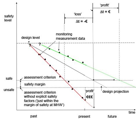
In the green situation, the calculated safety level derived from monitoring data is higher than in the design projection. This indicates profit from monitoring in favourable outcomes. In other words, since there are no costs incurred until a later period, savings can be achieved in the short term. The delta t shows the profit from monitoring, factoring in the ‘safety’ margin for possible delay of reinforcement after rejection of the dike. In the red situation, the barrier strength appears to be below the design projection. This creates a 'loss' due to expediting of reinforcement found to be necessary by monitoring data. In this case, profit from monitoring can still be gained in unfavourable situations. The €€€ shows the potential profit from breach prevention instead of (potential) loss from irresponsible exposure to flood risk.
The figure and explanation above is based on an interview with Mr A.R. Koelewijn (Deltares; 2012) and is currently under discussion. Comments regarding this topic can be left below the Delta Fact.
In 2010, the FloodControl 2015 project conducted a business case study on the use of sensor technology for dikes (Bultsma, 2010). It concludes that a cost-benefit analysis would be required and that profits can generally be made from monitoring dubious dike contractions (approved but just meets standard requirements or rejected), if the uncertainties involve time-dependent parameters such as water pressure.
Within the IJkdijk project, a business case study is currently underway for the use of sensor technology for dikes. Recently, a business case was developed at Waternet where a EUR 100,000 investment resulted in the cancellation of a 20 million investment for required reinforcements, thanks to/ owing to the underpinning provided by a new approach involving the application of sensor technology for rejected dikes (for more details, see experiences).
Lessons learned and on-going study
The publication “Inspection of flood defences: an overview of measurement techniques (STOWA, 2010)”, describes a comprehensive test about sensors in relation to the failure mechanism macro-stability. The figure at page 22 provides an overview of the inspection techniques per the information supplied by various suppliers.
Currently, there are several projects underway involving sensors in dikes: IJkdijk, LiveDijk, Digidijk, UrbanFlood and Flood Control 2015. The central focus of the research is the application and implementation of monitoring systems in daily management practice. This includes testing, validation and the introduction of new sensor inspection and observation techniques and the conducting of experiments.
The IJkdijk development programme involves various development steps from the initial technical assessment of the operation and applicability of measurement techniques for flood defences to the interpretation and forecasting of dike strength for risk management, reinforcement, management and maintenance. Each development step is briefly described below.
- Validation experiments
The primary goal in these projects is to determine which measurement techniques can provide a better understanding of the behaviour of flood defences, with specific focus on a number of failure mechanisms important for the Netherlands. The conclusions drawn in the validation experiments about the applicability of measurement techniques and the usefulness and need for dikes and specific failure mechanisms will serve as input for future LiveDijk projects. - LiveDijk
The IJkdijk Foundation will conduct a follow-up of the validation experiments specifically for the implementation of LiveDijk projects. The LiveDijk projects completed or currently being developed focus on stability and piping. A drought-sensitive peat quay is also being monitored, using the knowledge obtained from previous drought studies conducted by STOWA. - LiveDijk XL
Ultimately, it is not only the application of knowledge from dike technologies to measurement techniques that matters, but also the experience to be gained from scaling-up a few hundred metres to tens of kilometres of a dike system. One of the greatest goals in this regard is the challenges in IT systems, data processing and model-based data processing and interpretation, etc., specifically in relation to the possibilities of monitoring for reinforcements and risk management. - Dijk Data Service Centre
Out of concern for data fragmentation issues at the water boards, where all data are converted separately, efforts are being made to set up a Dike Data Service Centre (DDSC). It is important to streamline the processing of data from sensors as this will allow for real-time monitoring of dike stability in the future. The DDSC streamlines data acquisition and processing and makes data available to the managers in a simple manner. The data management system that eventually collects and streamlines all the monitoring data is the crown on the IJkdijk development programme. The core of the DDSC is designed and controlled by managers. Important applications can then be developed in cooperation with the private sector. The DDSC is still in development.
For more information about IJkdijk, see example of IJkdijk activities.
The IJkdijk Piping Experiment has provided a wealth of knowledge in the area of failure mechanisms of piping, its operation and the factors which ultimately determine failure. Piping and stability were the primary focus of the experiments, where water pressure was identified as a key parameter for piping, and water pressure and deformation as the key parameters for the incline stability; satellite information can provide additional information on this. Visual inspection, however, continues to be important at this time as it is needed to check unexpected events, non-instrumented parameters and possible sensor change/displacement, which inadvertently changes the measured value. Use of sensors alone will not provide a complete picture of the dike stability status (Hopman et al. 2011). A limitation of the piping experiment is that it is a hybrid between a laboratory and hands-on experience, but far from a real situation.
The UrbanFlood project examines the use of various sensors in flood defences in conjunction with an online early warning system (EWS). The EWS, which uses sensors in the flood defences to monitor the environment, provides early warning alerts and better information for water managers and emergency services. Modern software technology and geophysical calculation models allow abnormalities in the flood defence to be detected and transmitted rapidly. For water managers, this information is important for a realistic assessment against the standards for dike stability. In crisis situations, an EWS alerts water managers to critical dike conditions and possible consequences. The UrbanFlood technology automatically generates an EWS for a flood defence, whether it is 10m or 10km long. UrbanFlood can monitor dikes, anywhere in the world, from multiple locations at a time; as part of the UrbanFlood project, monitoring systems have been installed in dikes in and around Amsterdam, in Zeeland, in downtown Boston and on the English east coast and along the River Rhine nearby Rees, Germany. Brisbane is also being monitored. This ensures not only robust, nonstop vigilance, but also a better understanding of dike stability in terms of the reaction of dikes to ebb and flow, passing ships and vehicular traffic on the dike. Monitoring of the properties of dikes elsewhere generates knowledge that benefits the analysis of dikes everywhere. The presentation of real-time EWS analyses to various bodies at the same time uses Internet and web technologies which facilitate a coordinated decision-making process. UrbanFlood combines the knowledge of six partners from four countries (NL, PL, RU, UK), each an authority in its own field, from ICT to water.
Point-One (association of high-tech companies and knowledge institutes) examines the development of new sensors and the use of new parameter. At present, a number of high-tech electronics (measurement technologies) are being considered in terms of their capabilities for measuring the parameters relevant to flow slide and piping. Currently, Deltares is conducting a study for the Department of Waterways and Public Works to determine what knowledge is available about the physics of flow slide and piping, how the phenomena are caused and what exactly happens. In addition, attention is paid to identifying the measurable physical quantities and conditions (new innovative solutions) needed to allow for dealing with flow slide and piping more efficiently, The follow-up question to Point-One is this: how much would it cost to make sensors that can measure these physical quantities?
Further development of the 'DikeTool' programme as part of the FloodControl 2015 project will provide a unique (set of) warning and alarm values. In addition, it will improve the measurement series, allowing groundwater flow, piping and stability to be adjusted in order to reduce the uncertainty. An important sensor in this programme is the water pressure gauge.
At present, failure tests are being conducted at the North Holland Markermeer Dikes (Amsterdam - Hoorn, Hoogheemraadschap Holland Noorderkwartier) to determine the field strength value of the peat at the toe of the dike. Water pressure gauge, inclinometer, subsidence measuring hose and automatic subsidence marker are used in these tests.
TNO and the TU Delft have teamed up to develop a project for a satellite system for water applications: WaterSat. The focus here is on large-scale (> 500 nano satellites) measurement of deformations smaller than 1mm (height differences). FloodSat is also considering an expansion into an early warning system with sensor data from remote sensing.
At present, the development of the business case Digital Delta as part of Topsector Water project is also underway. Digital Delta studies the development of real-world examples of individual showcases involving water and ICT as a system infrastructure. The aim is to develop an infrastructure and platform to process and share measurement data. An important discussion within the business case is cost justification and who will bear the costs of setting up the infrastructure.
Knowledge gaps
Significant knowledge gaps in measurement technology are:
- what are the alarm values for the various parameters? Currently, there are no specific alarm values available. This is partly due to the measurement accuracies of the sensor techniques. This knowledge gap is being addressed within LiveDijk XL.
- how can the size of a measurement series (total duration, measurement frequency, spatial size) be valued? This knowledge gap is being addressed within LiveDijk XL and All-in-one sensor validation test (AIO SVT).
- how reliable is the information given the discrepant details about the composition of the subsoil, the lack of previous information on the load overflow and the lack of information on dike behaviour under extreme conditions? The uncertainties in the safety assessment are mainly found in:
- the water levels to be managed;
- subsoil structure (layer structure, presence and the gradient of channel sediment);
- properties of soil layers (volume weight, strength, permeability);
- water pressures in the dike and subsoil (phreatic line location, vulnerability to level variations in sand layers and effect of level variations in clay and peat layers) (Koelewijn, 2011). These knowledge gaps are being addressed within the Sterkte Belasting Waterkering (SBW, Strength and Loading of Water Defences) programme of the Department of Waterways and Public Works, underground railway modelling. - how often should measurements be taken to ensure that the obtained data are processed reliably and how can a reliable, semi-automatic alarm signal be obtained from these measurements? How does the system sound the alarm at the right time to allow for subsequent follow-up actions to proceed effectively? This knowledge gap is being addressed within the All-in-one sensor validation test (AIO SVT).
- The long-term measurement of specific components for the development of strength characteristics, deformation characteristics or revetment condition and the like. These reference sites support the development of empirical data specified above. Due to its specific character, this can be done on a small scale. This knowledge gap is being addressed within LiveDijk.
- The development of adaptive strength and condition models, which could ultimately provide a qualitative assessment of the condition of the flood defence or the water system:
- Absence of criteria to determine the value of a measurement series, since this depends on the total duration, frequency and quality of the measurements in relation to the events that have occurred (Koelewijn, 2011)
Example of IJkdijk activities
The IJkdijk, an initiative of N.V. NOM, STOWA, Stichting IDL/Sensor Universe, Deltares, TNO and the business sector, is a unique international project aimed at the development, testing and validation of sensor systems in flood defences. Over the past years, the IJkdijk Foundation has invested in knowledge development in:
- normative failure mechanisms (overtopping, macro-stability and piping);
- in-situ monitoring and sensor techniques, to a lesser extent in remote sensing techniques and airborne techniques;
- resilient sensor networks, data storage and processing and data representation;
- deployable sensor systems and scaling-up of such systems.
Heavy investment has also been made in market development by organising experiments in which market actors could participate;
The IJkdijk programme development steps are inextricably linked. With proper coordination and centralised management of project objectives, the needs and requirements of managers can lead to development of optimal products by companies in valuable showcases, which can result in international sales. Knowledge institutes contribute to the link between dike technology, measurement technology and ICT.
When the financing of the IJkdijk development programme is completed, the various development steps can be implemented. The development programme consists of the following steps and each step of the projects in preparation or development will be specified:
- Validation
The objective is to implement validation experiments and gain relevant geotechnical knowledge on sensor technology for flood defences. Validation is required for the final development of a sensor system that can be used for any application. In 2008 and 2009, the macro-stability experiment (1 test) and the piping project (4 tests) were implemented for this. One more experiment is in development for the Ijkdijk site in East Groningen: the Sensor Validation Test (SVT). During the SVT, which will be conducted in September 2012, four dike segments will be brought to collapse in accordance with the failure mechanisms macro-stability, piping, micro-stability and overflow, if applicable. The challenge for the monitoring companies will be to diagnose, locate and forecast the correct failure mechanisms. Then, in 2013, a flow slide experiment will be carried out at a designated location. - LiveDijk
As a follow-up step to the validation, the IJkdijk Foundation will partner with managers to carry out a limited rollout of the validated technologies to the management practice. A small-scale rollout will take place in LiveDijk projects. There are several projects in progress or preparation, including:
- LiveDijk Eemshaven (Noorderzijlvest water board)
- LiveDijk De Veenderij (Waternet HH Amstel, Gooi and Vecht. Combination of Validation and LiveDijk)
- LiveDijk Utrecht (HH de Stichtse Rijnlanden, Province of Utrecht, Department of Waterways and Public Works, Utrecht)
- LiveDijk XL Noorderzijlvest (Noorderzijlvest water board, see also point 3)
- Vlaardingsekade (developed by HH van Delfland)
- Stammerdijk (Waternet, UrbanFlood)
- Ring Dike (Waternet, UrbanFlood)
The LiveDijk projects are harmonised to ensure that development objectives are coordinated effectively. Objectives of the LiveDijk projects are broadly similar in nature, i.e.:
- Determine for managers the usefulness and necessity of monitoring systems for specific dikes (in relation to management, maintenance, reinforcement, safety assessment, etc.)
- Determine the prolonged functioning of sensor technology under field conditions;
- Demonstrate that installation and operation of sensor technology in an existing dike body can be achieved without causing the dike to 'fail'
- Demonstrate that 'background' noise due to environmental factors can be separated from loading factors relevant to the failure mechanisms of the dike
- Develop a real-time monitoring system to monitor the strength of the dike bodies by connecting the sensor technology to a central data centre and distribution of data to the workplace of the dike inspector, managers and other stakeholders in the water board. - LiveDijk XL
Scaling up to LiveDijk XL is the next step. Here, the knowledge gained in the smaller LiveDijk projects will be scaled up for application across long dike trajectories (several kilometres) to typical Dutch dikes. In both LiveDijk and LiveDijk XL, implementation plays an important role in the management practice (technical, organisational, process and plan-based practices) of water boards and the Department of Waterways and Public Works. The Noorderzijlvest LiveDijk XL project has been developed in collaboration with the Noorderzijlvest Water Board. After LiveDijk XL, the knowledge and products will be developed to such an extent that national and international marketing will take place on a larger scale. The project objectives are:
- Monitoring safety (early warning/early detection) of rejected dikes until improved. This objective will be met through the measurement data obtained through close collaboration with the Dike Data Service Centre and the models used for strength calculation and forecasting.
- Provision of additional information about the soil and dike structure and groundwater properties for the improvement activities. Here, a link can be established with the flood protection programmes and the consideration whether optimisation of reinforcement designs can be realised with the obtained monitoring results. This will be investigated together with the Flood Control 2015 programme.
- Monitoring of dike sections and after the improvement activities, partly in preparation for management and maintenance.
This is a long-term objective. Savings in management and maintenance are difficult to estimate. However, significant savings are projected in the safety assessment costs. - Dijk Data Service Centre
The validation and LiveDijk (XL) projects provide much information that can be used as reference for similar dikes in other locations. A data storage, processing and analysis system - Dike Data Service Centre (DDSC) - is being set up in North Holland. With the development of the data management system it will be possible to make real-time analysis for gaining real-time understanding about dike strength and forecasting of dike strengths (e.g. with the prospect of a flood or storm event). The DDSC makes the objectives of the various LiveDijk projects possible.